Worked example: Slotted block sonotrode with 3 probes
 A common ultrasonics application involves driving several probe sonotrodes from a single large block. This arrangement allows for a significant step-up ratio and wide separation between the probe tips. This article goes step-by-step through the process of creating a model of such a system in SonoAnalyzer and optimizing its performance.
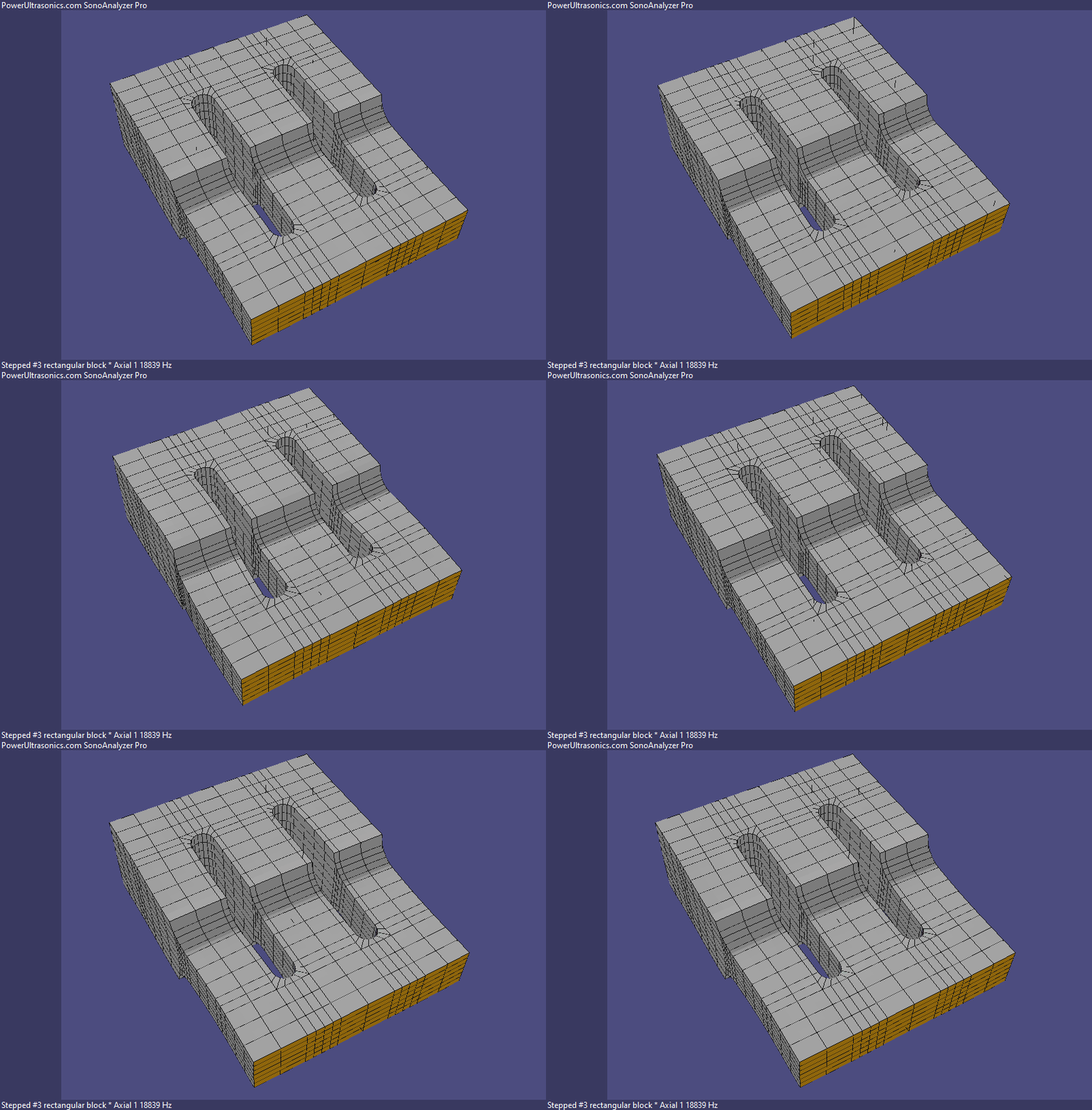 For this simple example I've started with the SonoAnalyzer standard slotted stepped rectangular block. Using the default dimensions (124mm long) and choosing material aluminium L168, the analysis shows the Axial 1 mode at 18839 Hz.
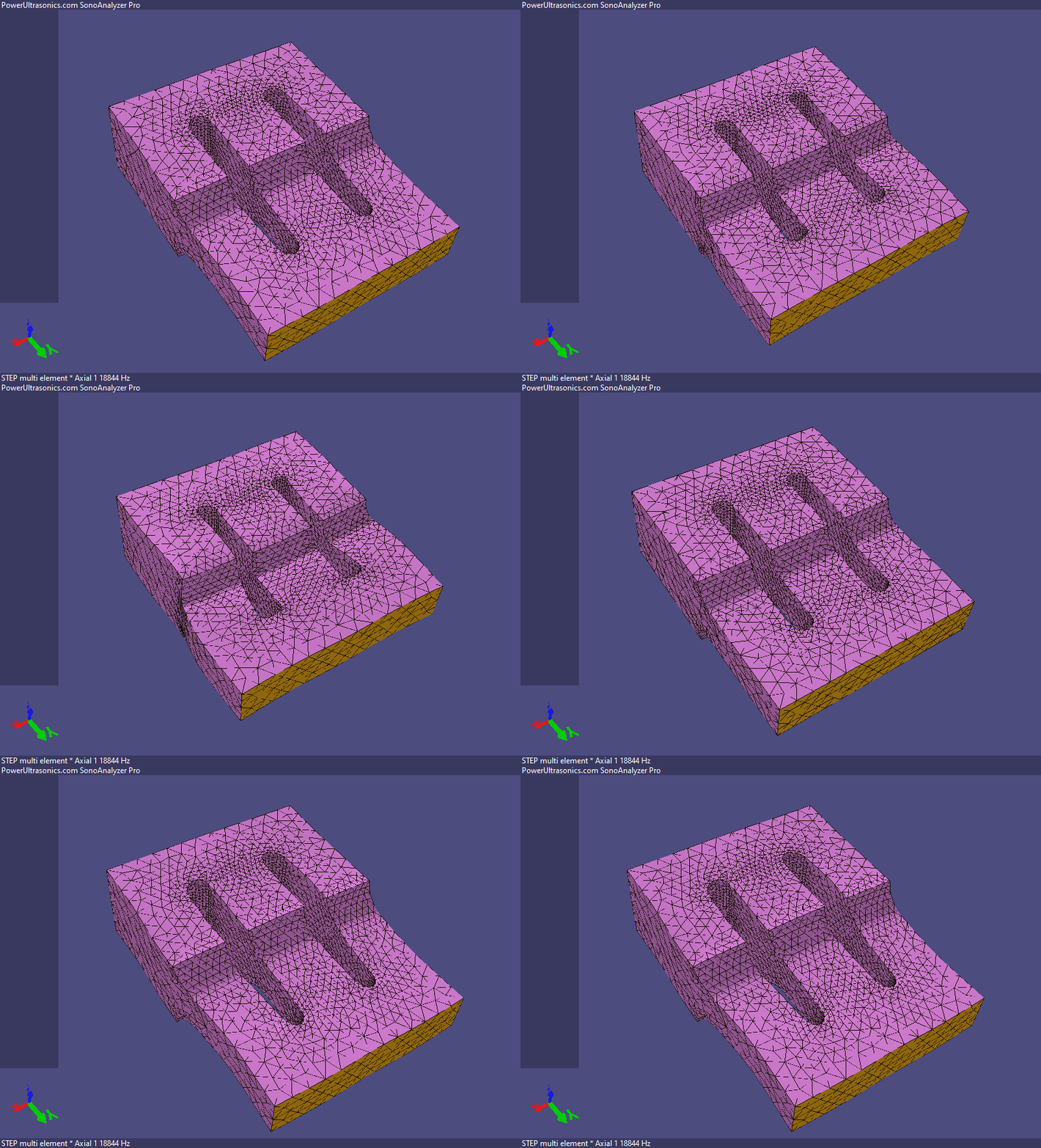 After exporting the STEP file and importing it into the STEP multi-element analysis a very similar result of 18844 Hz is obtained. So assuming we're aiming for a 20kHz system this needs a bit of tuning. On the new STEP multi-element model we can do this using the trim function, so here in the Trim[1] selector I've selected +y, which it helpfully labels "output". (I could equally well choose Trim[2] and the result would be the same. A second trim selection is for situations where we want to trim in more ways than one.) I started with a trim of 5mm, just to get somewhere close to the target 20kHz frequency, and then used the auto-tune function.
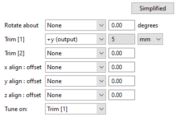 Note that when using auto-tune on the new analysis type we also have to tell it exactly what to adjust - in this case Trim[1] - by selecting it in the "Tune on" option for the component we want to adjust. The analysis takes a few minutes but once it's done we find that Trim[1] has been adjusted to 5.10 mm and the Axial 1 frequency is 19980 Hz. Close enough.
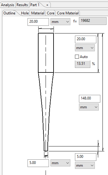 Now for some probes. The output surface of the block is 20mm wide so we want the probe input diameter to fit within that. I've choosen an exponential profile to get lots of output amplitude without excessive stress. But whatever the profile this will be a highly stressed component so it makes sense to choose a titanium alloy for this application. I've chosen the standard Titanium 6Al 4V material. After a little experimentation with the dimensions I chose a length of 148mm, giving an Axial 1 frequency of 19681Hz from the "Exponential #4" analysis type. The geometry is then exported as a STEP file.
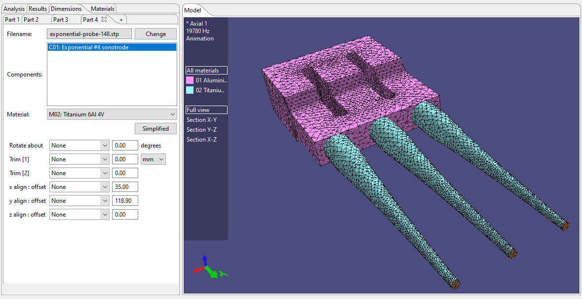 Next that STEP file is imported into the multi-element analysis and used for all three probe components. The advanced positioning options are used to position the probes on the output surface of the block. Because both STEP files have been created by SonoAnalyzer they are both aligned on the y-axis with the origin in the centre of the input surface, so to position the probes we need to offset their y-coordinate by the length of the block sonotrode, which is (124-5.1) = 118.9 mm. So all three probes are given a y-offset of 118.9mm, and the x offsets are set to zero, -35mm and +35mm, giving the separation across the output surface of the block.
 To run the analysis one further special setting is required. The complete assembly is relatively large with some flexibility in all three probes, which gives rise to multiple low-frequency resonances, so the SonoAnalyzer default of extracting the first 30 modes is not sufficient. A setting of 100 modes, along with minimum and maximum frequencies of 15000 and 25000 Hz respectively, works well.
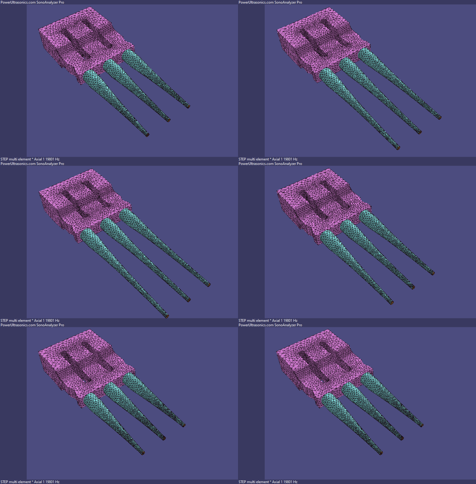
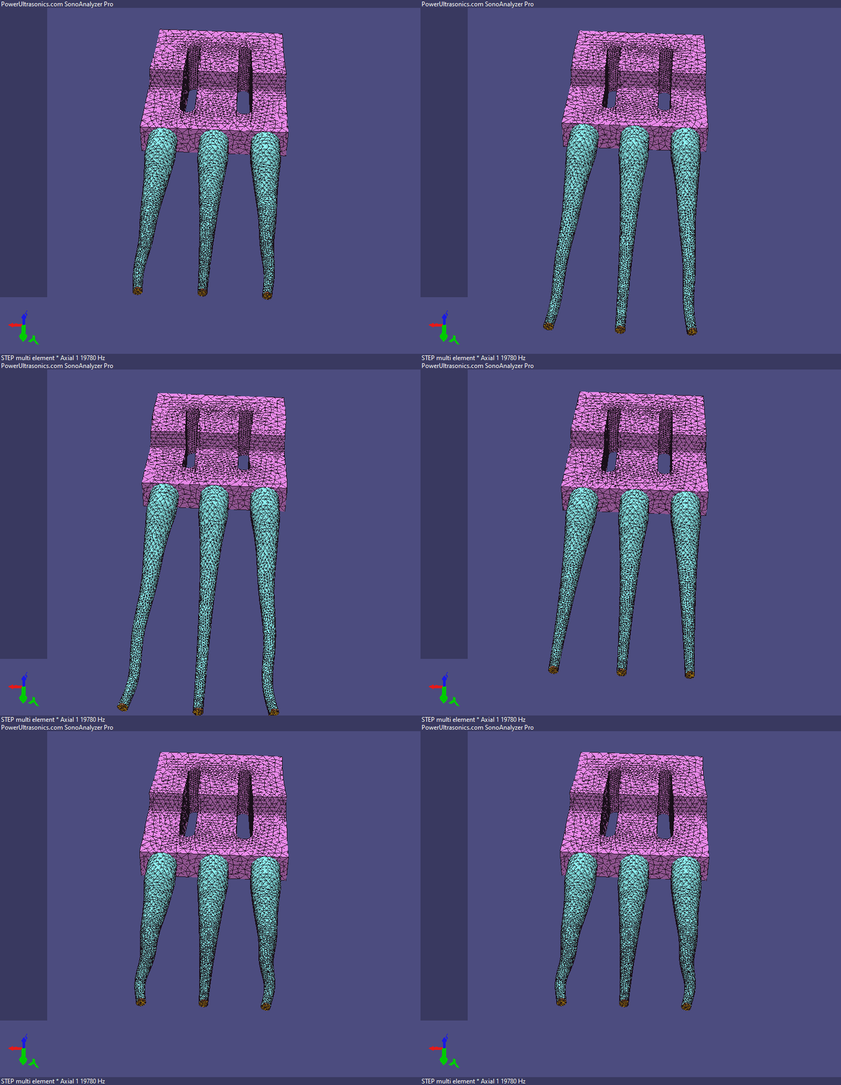
 With that done the analysis identifies the Axial 1 mode at 19.78kHz, normally a good result, but here a problem is apparent: the two outer probes have a very non-uniform amplitude at their tips. This is often seen on assemblies like this - slight non-uniformity at the edges of the block sonotrode is magnified through the probes, giving a very unsatisfactory output.
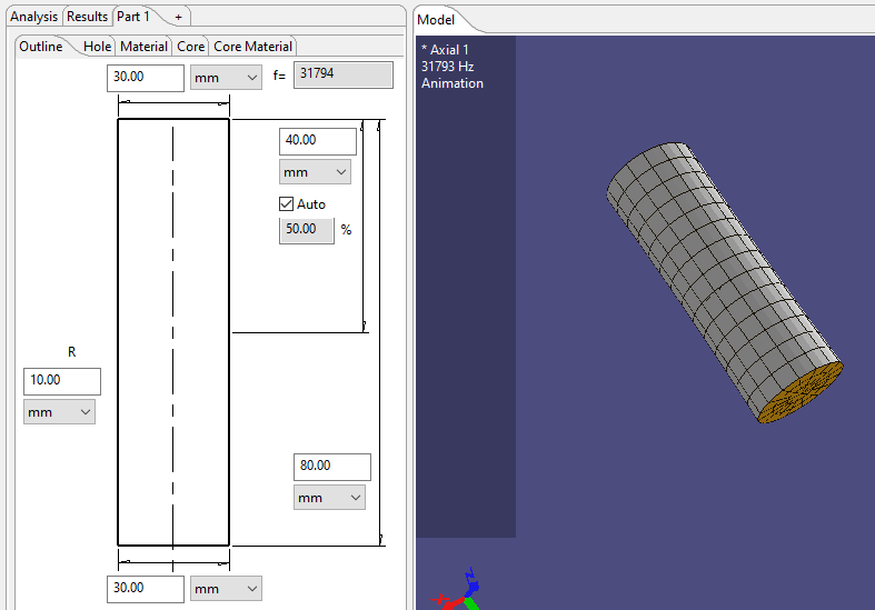 To improve the uniformity of amplitude across the output surface of a rectangular block, a common technique is to machine small grooves in the outside edges of the block. With the new STEP multi-element analysis we can model this by cutting a cylindrical surface from each side of the block. We could design this cylinder in any CAD program but it's also simple to create from within SonoAnalyzer, eg. stepped cylinder with both input and output diameters set the same. I created one 30mm diameter, 80mm long, ran the analysis (it just takes a few seconds) and exported a STEP file.
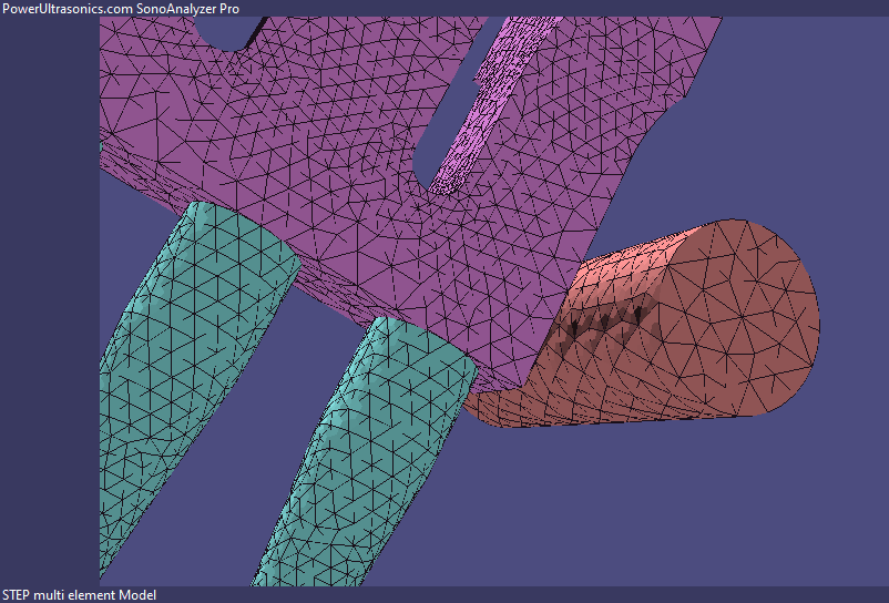
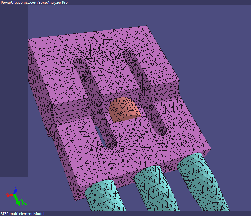 Now we switch back to the multi-element 3-probe analysis and import the STEP file as a new element. For illustration here I've used a third material (Stainless steel) for the added cylinder to show where it's positioned by default - embedded in the input section of the block.
Obviously this is not what we need, so again the advanced positioning options are required.  First a 90 degree rotation about the x-axis aligns the cylinder as we want, and then x, y and z offsets of -65mm, 100mm and -40mm respectively place the new cylinder just touching the side of the block sonotrode in roughly the position needed to produce the desired groove. Note that an x-offset of 65mm will leave the block untouched; reducing to 60mm will produce a 5mm deep groove, and so on.
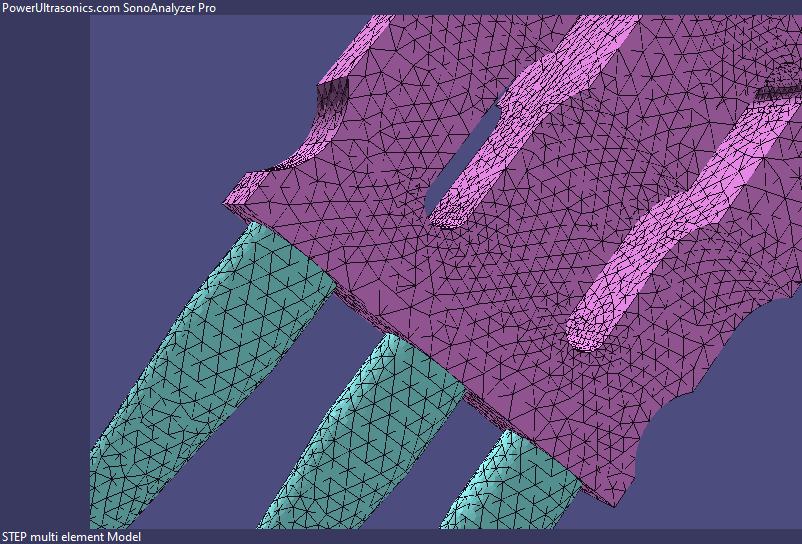 The final step is to change the material type for this cylinder to "Subtract" and add another element which will be identical except for the reversed x-offset. Here offsets of plus and minus 60mm are in use. At this point we could re-run the analysis and look for any improvement, but it's very likely that multiple analysis runs will be required and each run (including the increased number of modes) takes a significant amount of time, so is there a more efficient way?
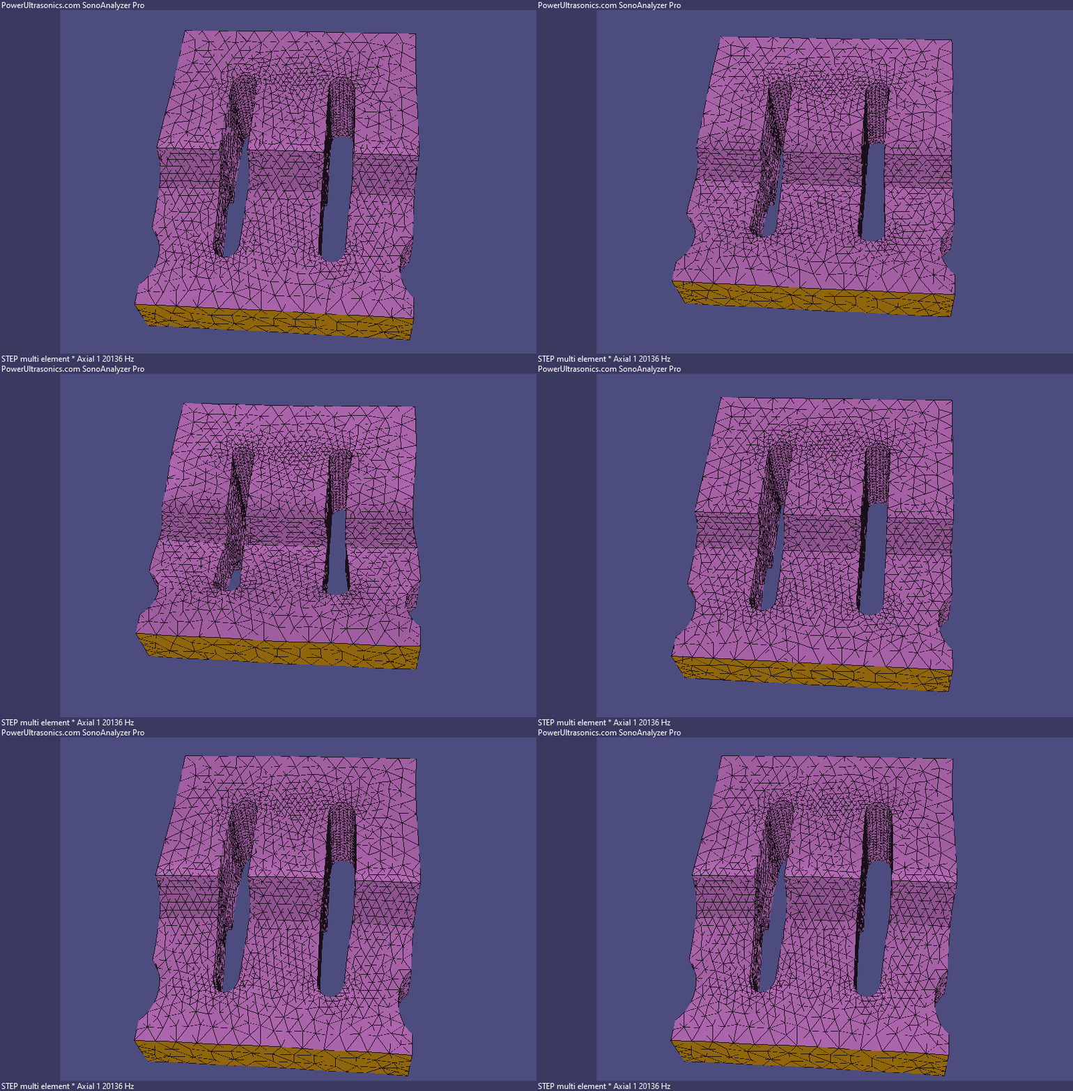 One option is to remove the probes and analyze the cut block alone. In this case we can revert to the default 30-modes analysis and there are also much fewer nodes and elements so the analysis completes much more quickly - typically within a minute or two. Comparing the animated view against the earlier model without the side grooves, it's difficult to tell the difference.
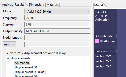 A new feature in SonoAnalyzer version 2.3.2 can help here. The motion on the output surface is analyzed to calculate two figures of merit to evaluate its uniformity. The M figure relates to the variation in magnitude of the axial component of amplitude, while the D figure is derived from the maximum directional deviation. For larger sized sonotrodes it's common to have lower values for the directional figures because lateral motion is caused by the elastic material properties (notably Poisson's ratio).
In this case the result shows M: 92.4% D: 62.3%, compared to M: 93.5% D: 95.8% for the original model, so in this case the grooves have not improved performance. But perhaps shallower grooves would work better? Repeating the analysis for offsets at 1mm intervals shows this:
60mm M: 92.4% D: 62.3%
61mm M: 96.0% D: 73.8%
62mm M: 96.3% D: 84.1%
63mm M: 95.5% D: 92.1%
64mm M: 94.1% D: 97.2%
65mm M: 93.5% D: 95.8% (no groove)
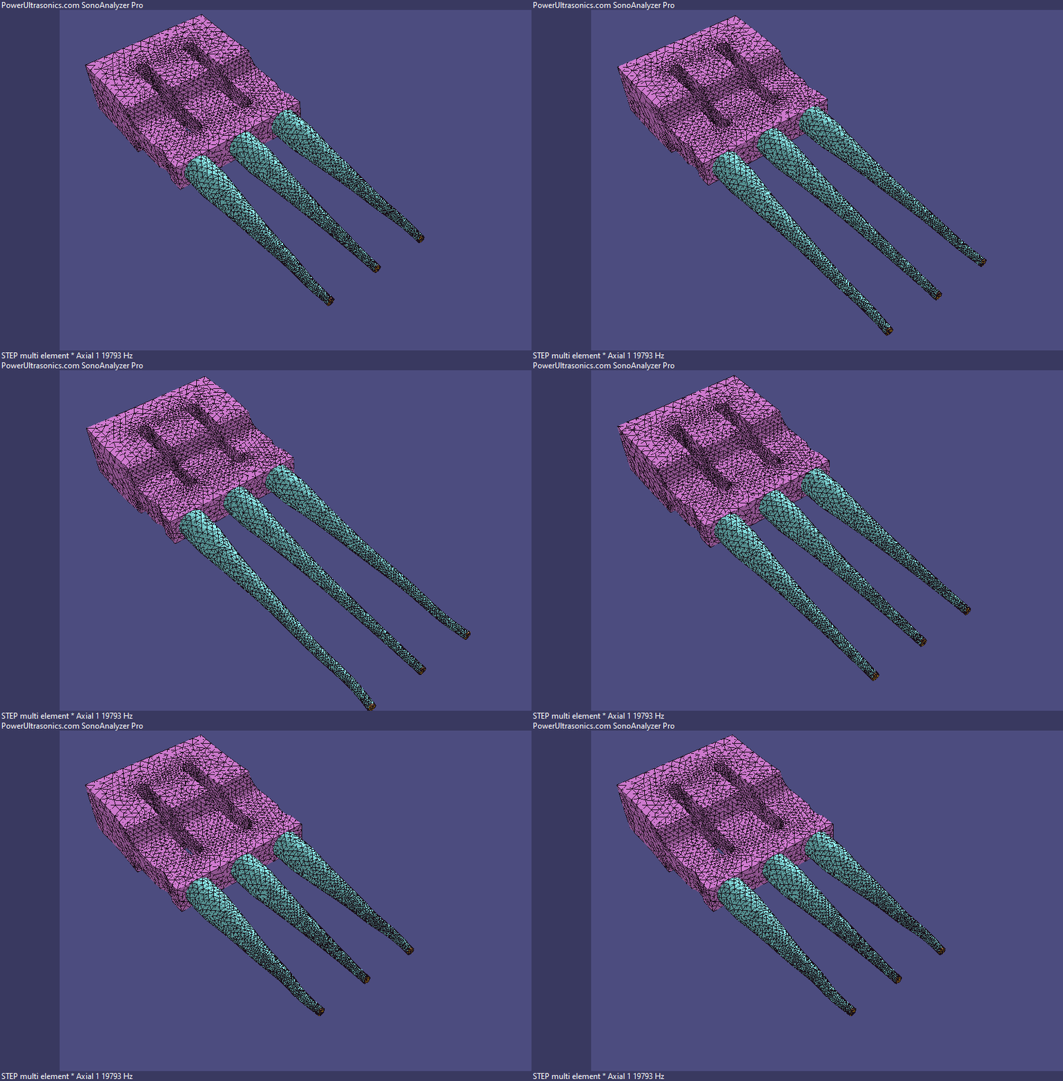 This is an interesting (and somewhat frustrating) result where the optimal value for magnitude variation is 62mm whereas for directional variation it's 64mm.
From past experience the magnitude variation is more important so here I would try 62mm or 63mm as an offset value for full analysis.
At 63mm the result is noticeably better than the original design but there is still some unwanted deflection of the outer probes but at 62mm the deflection is virtually eliminated.
Clearly the optimization process could continue with variations in the y-offset (position along the length) and radius of the groove but I think this is sufficient to demonstrate the process.
On completion File -> Export -> 3D model (STEP) will produce a combined STEP file with all geometry modified by tuning and cuts. Optionally this STEP file can be re-imported to form the basis of a new analysis using the final geometry with all advanced options disabled, or as a start point for further optimization.
A package of results files generated during this process will be available soon from the downloads page, allowing users of version 2.3.2 (including SonoAnalyzer OE and Free editions) to view all analysis results directly within SonoAnalyzer.

