SonoAnalyzer Pro version 2.3.0 (beta)
 Announcing the long-awaited release of a new SonoAnalyzer Pro, version 2.3.0 beta. This introduces a new, much requested model type called "STEP multi-element". As the name implies this allows combining multiple STEP files containing geometry, or a single STEP file containing the geometry for multiple components, or both. No matter how the component geometry is defined, different materials can be selected for each individual component. As this is a beta release and the new model type is for SonoAnalyzer Pro only, new versions of SonoAnalyzer OE and Free will not be released this time.
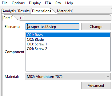
To demonstrate the new model type a simple demo model is included in the SonoAnalyzer Pro package. This is a concept for an ultrasonic scraper with a common utility-knife blade clamped into an aluminium stepped sonotrode using two small screws. All four components are defined in a single STEP file and entered as three geometry sub-tabs in SonoAnalyzer (one tab for each material - the two screws are selected together on the third tab).
In the SonoAnalyzer graphics window there is an additional option for this new model type only: Single material display. On the geometry view (alfer redraw, before analysis) and on the animation view (after analysis) the area on the left of the graphics window, normally used for a key on contour plots, now shows a list of materials used in the model. Click on any one of the material labels to show only that material, or click on the "All materials" label to return to the standard view of all components. This feature works alongside the existing sectional views (double-click on the graphics window to toggle through available sections).
Some deprecated features are not available in this model / version, notably external graphics using the CalculiX cgx program, .stl file import and the use of Netgen for mesh generation. If any users have a specific need for these please contact me to discuss your options.
To support the new analysis, new pro analysis servers are also required (designated v3, replacing the earlier v2 servers). For cloud-server users there is an option within SonoAnalyzer to request an upgrade - just click the OK button on the warning popup that appears when the new model type is selected with a v2 analysis server. For users of locally-installed analysis servers a new Windows binary will be available to download shortly.
As always, if you find any issues please let me know. More details follow.
 New UI:
The new model features the same building blocks as previous versions but in a different arrangement, giving increased flexibility required for multiple geometries and multiple materials. The four top-level input tabs will be familiar to users of older models: Analysis, Results, Dimensions, Materials. But under the Materials tab there may be up to 10 sub-tabs where user can define a "pallette" of all materials to be used in the model. Then under the Dimensions tab more "Part" sub-tabs define the geometry to be analyzed and a selection box for the material to be used. In addition to a material selection the special option "Subtract" is also available. As the name implies this flags the selected component geometry to be cut from the remaining parts. This could be used for example to cut a special profile into a simple shape.
Multiple STEP files vs multiple components in a single STEP file:
In the earlier STEP-import model type, if the STEP file contained more than one compoent, SonoAnalzyer would load and analyze only the first component, ignoring all others. With the same file imported into the new model type, SonoAnalzyer will now process the file, detect the multiple components and present them to the user for selection in different materials. Defining components in this way is highly recommended since the relative location of each component is pre-defined by the user. Alternatively further STEP files can be loaded and components within those files will be presented for the user to select.
 Advanced positioning options
Additional options for aligning and positioning components relative to each other will be available in a later release, accessible via the "Advanced" button on the part tab.
New analysis servers:
The new analysis includes a series of geomety processing operations to identify and manipulate the components defined in the user's STEP files. This work requires a newer version of FreeCAD than previous analysis servers included. The meshing also benefits from a newer gmsh version. New analysis server packages, designated v3, are available for the online "cloud" servers provisioned to all current Pro users or as a Windows binary for download. In the interest of simplicity some functionailty associated with deprecated SonoAnalyzer Pro features has not been included in these packages.
- CalculiX cgx is no longer a modified version allowing remote-control through SonoAnalyzer; instead a standard version is used (version 2.17 to 2.21).
- Cygwin/X (used for interactive graphics in CalculiX cgx) is no longer included in the Windows binary.
- TigerVNC server (used for viewing CalculiX cgx graphics on a remote server) is no longer included in the cloud servers.
- Netgen is not included in any v3 analysis servers. Gmsh was already the preferred option for STEP imports; it is now a requirement.
So when connected to a v3 analysis server all operations under the FEA menu (which rely on connecting to cgx) will no longer work: Mode animation, Displacement plot, Axial displ plot, Stress plot, Capture current. These functions were deprecated already as the standard SonoAnalyzer graphics have provided equal or greater functionality since version 1.7.1. From this version 2.3.0 all FEA menu options are disabled when connected to a v3 server.
Usage:
First create geometry in your preferred CAD program as a number of separate components and export this model in STEP format. Meaningful names should be used for the components.
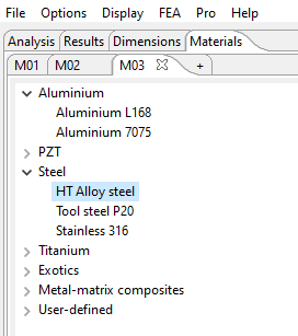
To start a new analysis in SonoAnalyzer, first click on the "Materials" tab and in the sub-tabs labelled M01, M02 etc, select all the materials you want to use for the analysis. As usual preset materials are available or custom / user defined materials can be set up by defining the elastic properties. Then go to the "Dimensions" tab and remove all parts other than Part 1 by clicking the X in the tab title. In the "Part 1" tab, click the "Change" button and select the STEP file you exported from CAD. After a new file is selected for analysis the message "Please wait for STEP file checks" will be displayed briefly, while SonoAnalyzer evaluates the components contained in the file, reading their names and extents (the range of x,y,z values covered by the geometry) and presenting them for selection in the "Component" multi-select list. Select one or more components and in the "Material" selection box, choose a suitable material. Next click the "+" tab to the right of the other part(s). The new tab is automatically populated with the same STEP file and components list, so another component can be selected and another material. And this continues until all components have been selected. Now click "Redraw" (or wait for timeout) and SonoAnalyzer will proceed to create a multi-material mesh, displayed on screen in different colours for each material. Having checked that the geometry is all as expected, click the "Analyze" button to run the FEA analysis (as for previous Pro models).
If all geometry is not defined in the one STEP file then another file can be used in the same way, using the "Change" buton and selecting the new file. Note that the components in the two files must be correctly positioned relative to each other. In a future development options for automatic alignment will be added.
Contacts, gaps, overlaps:
Where two components have a contacting surface the mesh created will link them across that surface. This can be imagined as gluing them together using an infinitely strong adhesive. Where there is a gap between nearby surfaces (I suggest at least 0.05mm) the surfaces will not be connected and will be free to move independently. In the animated results display (which greatly exaggerates the motion) such surfaces may well overlap during part of the cycle but this doesn't represent reality - it's just a display effect. Where different components really do have overlapping geometry such overlaps will be eliminated before meshing, leaving the components in contact.
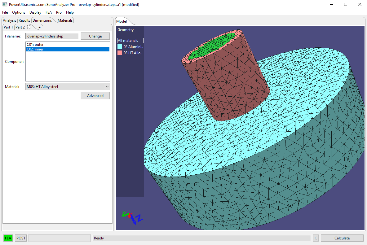
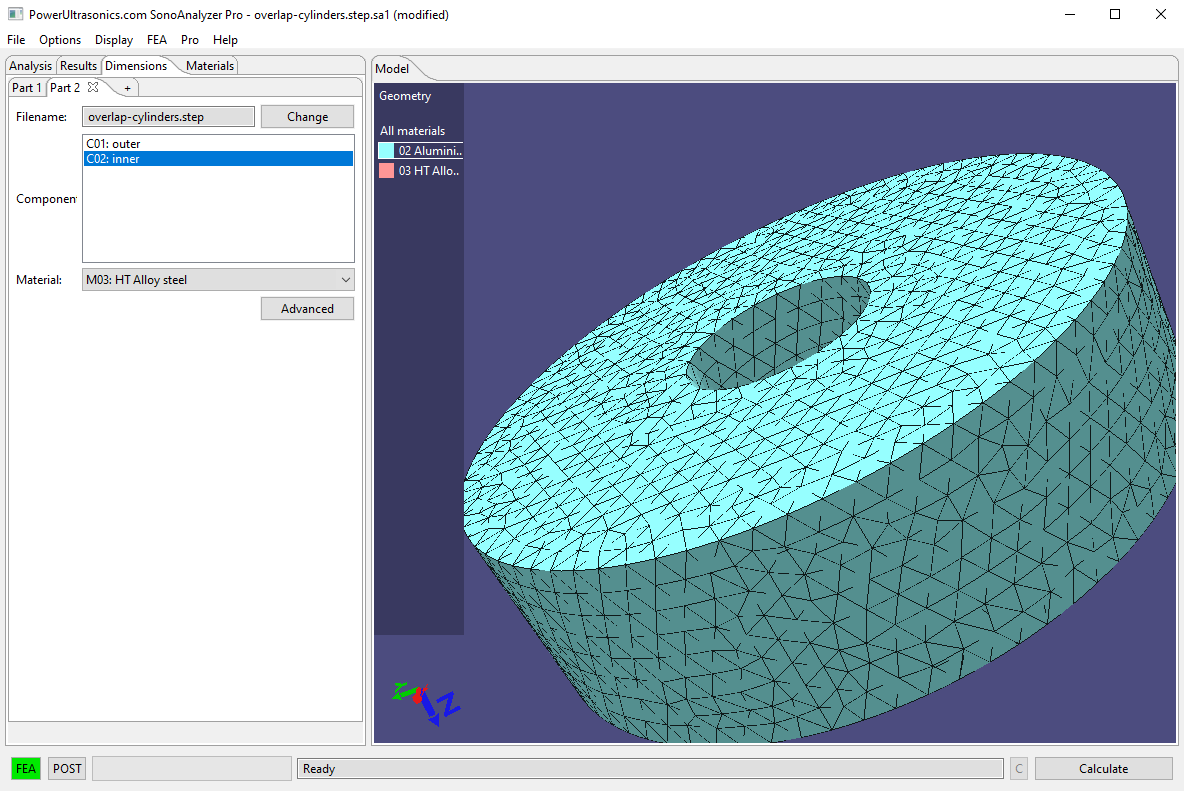 Where an overlap is found the component defined later will maintain its shape while the one defined earlier will have the overlapping section cut out.This is demonstrated in the STEP file "overlap-cylinders.step", available from the downloads page.
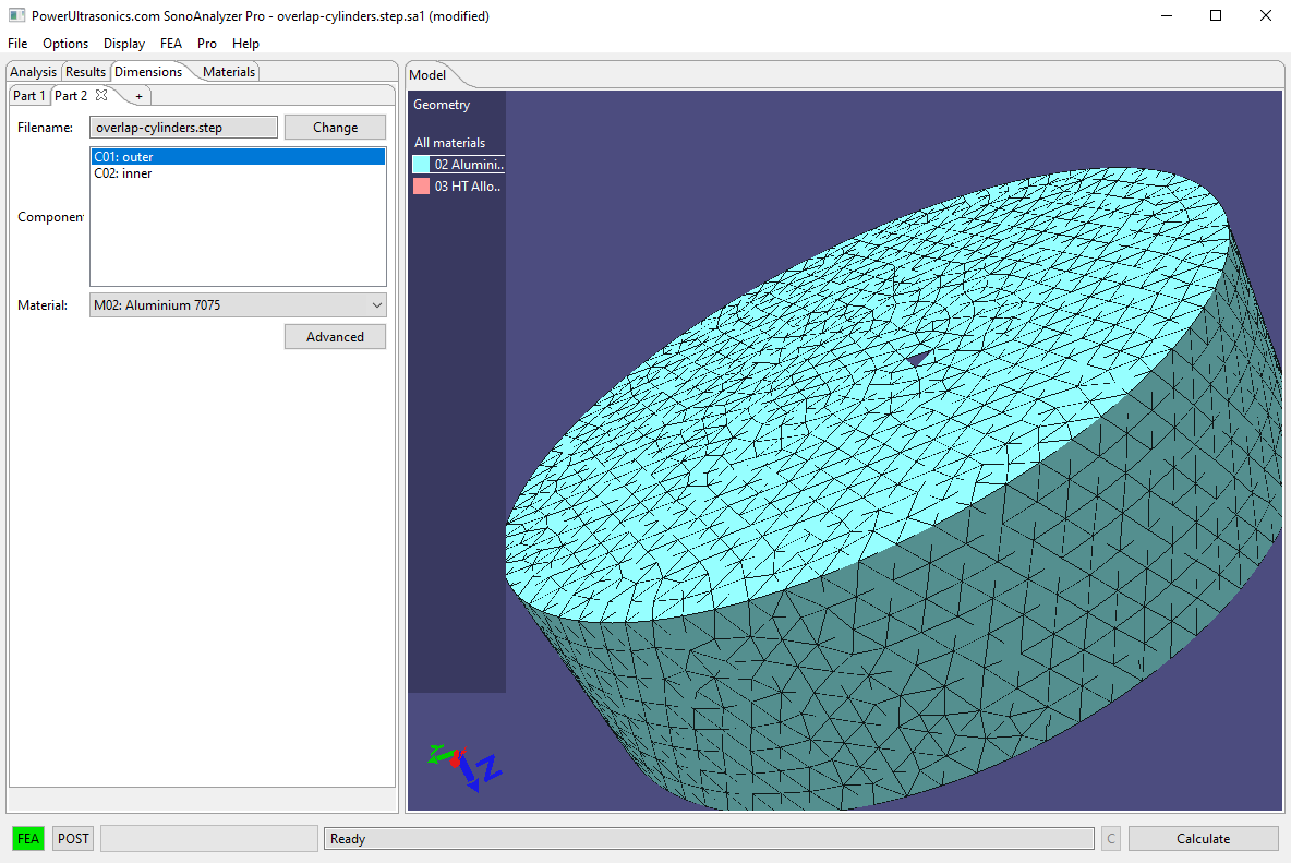
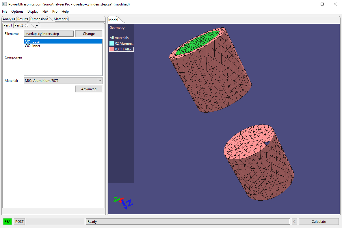 This features a solid inner cylinder (longer, with a smaller diameter) and an outer cylinder (shorter, with a larger diameter). If the outer cylinder is defined first, as Part 1, and the inner cylinder as Part 2 then during processing the inner cylinder will be left intact while the outer has a hole cut through it. Conversely if the inner cylinder is defined first, as Part 1, and the outer as Part 2 then the outer will be intact and the inner will be cut into two parts.
How it works:
The new model type uses geometry processing provided by FreeCAD, meshing by Gmsh and FEA analysis by CalculiX ccx, all open-source software provided in the FreeCAD distribution package. The CalculiX pre- and post-processor cgx is not used for this model type but is included in the analysis servers to support earlier models.
Note: the "Smooth midside nodes" option is not offered in the new model type since second-order geometry (correctly placing mid-side nodes on curves) is now generated directly in Gmsh.
Information for new purchasers (Pro):
New purchases will be provisioned with version 2.2.0 software and version 2 analysis server as standard. This version 2.3.0 will also be available to download for users who want to try the new functionality. For those running 2.3.0 the corresponding upgrade to a version 3 analysis server will be available on request. Version 1 is no longer offered or supported.
Running a version 3 Pro analysis server is a requirement to us the new model type. For other analyses and the previous version 2.2.0, one that includes the Gmsh mesher is strongly recommended. All current cloud servers do provide this. Users wishing to run their own standalone servers should install the latest version of the FEAServer setup.exe file, currently 2.0.2, from the downloads page, or see full details here.
For information on all available products please see the purchase page.
Information for new purchasers (OE):
New purchases will be provisioned with version 2.2.0 software.
These new STEP-import models are not available on SonoAnalyzer OE, only on SonoAnalyzer Pro.
For information on all available products please see the purchase page.
Information for current license holders (Pro):
Updates are included with your original purchase for one year. Within that time the new download can be found in your user account under the "Files" tab. On Pro, the new file is named "SonoAnalyzerPro2.3beta-setup.exe". If you do not see the need for the new model type then there is no reason to upgrade.